Project 8.1a Model a Miniature Train
Introduction
Have you ever ridden on a train or owned a train set? The parts that make up the engine car on a train can vary depending on the make and model; however, all train engine cars have parts that are similar.
Interpreting dimensioned drawings is an important engineering skill. Using drawings to create a computer model of a part is also important. You learned earlier in this course that a sketch is the documentation foundation for related technical work. Communicating this information effectively allows a group of people to function as a design team.
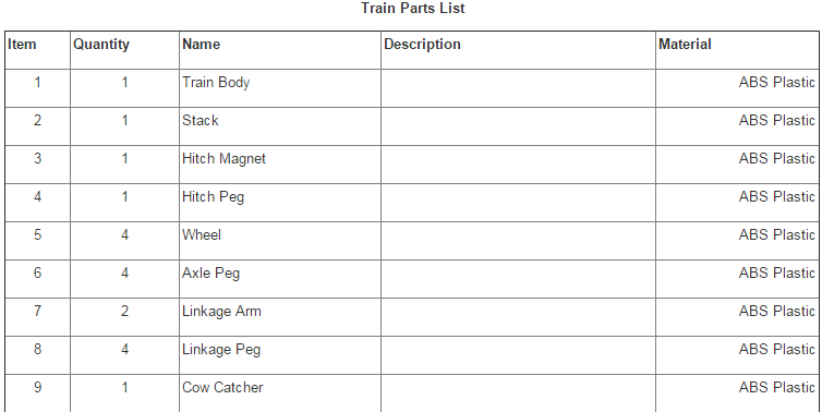
In this project you will further develop your modeling skills and your ability to use a computer as an efficient communication tool. The skills that you learned earlier in this course will be systematically applied to model the eight remaining parts needed for the Miniature Train Assembly. The parts with the dimensions are listed below.
Equipment
Procedure
1. Model and assemble the parts shown using the drawings provided.
2. Create a set of working drawings to document the train parts and assembly.
Have you ever ridden on a train or owned a train set? The parts that make up the engine car on a train can vary depending on the make and model; however, all train engine cars have parts that are similar.
Interpreting dimensioned drawings is an important engineering skill. Using drawings to create a computer model of a part is also important. You learned earlier in this course that a sketch is the documentation foundation for related technical work. Communicating this information effectively allows a group of people to function as a design team.
In this project you will further develop your modeling skills and your ability to use a computer as an efficient communication tool. The skills that you learned earlier in this course will be systematically applied to model the eight remaining parts needed for the Miniature Train Assembly. The parts with the dimensions are listed below.
Equipment
- Computer with 3D CAD solid modeling program
- Engineering notebook
Procedure
1. Model and assemble the parts shown using the drawings provided.
2. Create a set of working drawings to document the train parts and assembly.
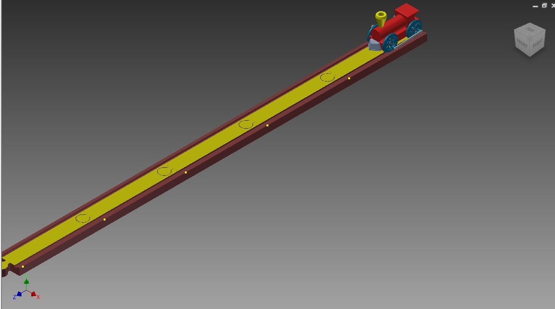
Train Track Assembled (Not Complete)
Conclusion
1. Why are drawings composed of different line conventions? Drawings are composed of different line conventions so you can easily and properly dimension the part the drawing shows.
2. What is the purpose of a sectional view? A sectional view allows the engineer to view all dimensions to a part with ease and without a whole lot of confusion or scattered numbers.
3. What is the purpose of an auxiliary view? An auxiliary view allows an engineer to see 3 different sectional views and an isometric view of the object. It helps the engineer easily choose a starting plane as well, based on how the object is positioned in the view.
4. Why are symbols used instead of words to identify hole types? Mainly for keeping the sketch clean and it also makes the sketch's communication easier.
5. What advantage is there to using algebraic equations instead of numerical values when defining the dimensions of a CAD model? Using algebraic equations over numerical values when defining CAD model dimensions can help skip dimensioning and save time.
6. What three types of constraints can be applied to CAD sketches or models? There are motion constraints, assembly constraints, and geometric constraints.
7. What advantages do CAD drawings have over paper sketches? CAD drawings allow an engineer to easily place lines, apply geometric constraints, dimension properly, etc...
